[av_textblock size=” font_color=” color=”]

57white (1)Roller Tappet Cam Engine

Presenter: Doug Prince

Doug’s Tip of the Day:  Per Doug Prince you should not use any new oils with the “Energy Conservation” seal! These newer blends remove zinc which is a lubricant needed to lubricate highly loaded flat cam lifters which are used in these early 6 cyl. engines. No problem with later engines and with roller cam mods. I found that Pennzoil 10W-40 is not an “Energy Conservation” oil. 

Roller Tappet Cam (RTC) technology is a deviation from the technology employed into the original C1 engines.  The differences of this technology is explained below but the intention of Doug’s presentation is to outline an RTC into a “stock appearing” C1 engine.  The advantages of a RTC engine is major reduction of internal friction and increases in horsepower.

The final portion of this Forum is a compiled list or parts by the Presenter (Doug Prince) to build a RTC engine.  This task is recommended by the presenter to be accomplished professionally.  Doug’s recommendation is:

Quarter Mile Performance, aka, QMP Racing Engines

Brad Lagman, Owner

9530 Owensmouth Av.

Chatsworth, Ca. 91311

(818) 576-0816

Camshaft/Valve-train Basics 101
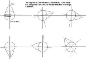
The camshaft purpose is to provide a mechanical method to open in close the intake and exhaust valves inside our engines combustion chamber.  Each combustion chamber contains two valves.  The intake allows a fuel/air mixture to enter the chamber and the exhaust allows combusted gases to exit out of the chamber.  The timing of this process in the V8 engine is controlled by the camshaft and ignition timing.Camshafts are essentially a “stick/rod” about the length of the engine.  Camshaft/sticks have a basic diameter which support the camshaft inside the engine (5 points indicated in the figure below).  Along the camshaft length are “lobes” (16 in the case of a V8) which extend beyond this basic diameter.  At the front end of the Camshaft is an “extra” lobe which actuates the V8Chev fuel pump.  The fuel pump arm is activated by a solid rod which rests against the pump arm and “rides” on the cam fuel pump lobe.  At the rear end of the cam is a gear whose purpose is to engage the ignition distributor shaft gear and also drives the engine oil pump.

File0001w

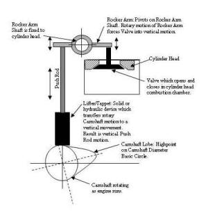
The following figure illustrates as the camshaft rotates the lobes will rotate and push against a Lifter/Tappet transferring the rotary camshaft motion into a linear up/down motion of the tappet.  The linear tappet motion continues by moving a push rod up and down exerting a force on a Rocker Arm.  The Rocker Arm rotates/pivots on a shaft located external to the cylinder head.  Some designs have pivot bolts instead of Rocker Arm Shafts but the function is the same.  Another variation is a flathead engine which does not use Rocker Arms and the valves located in the engine block are directly opened and closed off the Lifter.  As one end on the rocker arm is forced vertically, the arm pivoting action moves the other end in the opposite direction.  This other end than transfers the motion to a Valve and depending on the direction of movement moves the valve off or onto the valve seat, i.e., open and closes the valve.

Camshaft-Rotationw    Camshaft-Rotationw2

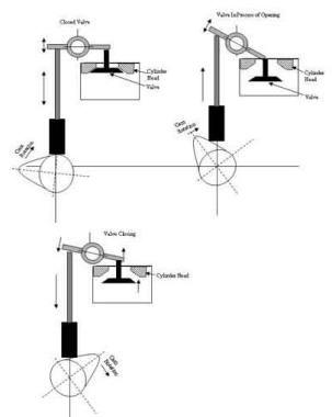
Illustrations to the right indicate the rotating cam lobe causing the valve action to open and close.  The one item not shown in this illustration is that a valve spring continually forces the valve against the valve seat until the mechanical action of the cam lobe forces the valve to unseat.  As the cam lobe continues to rotate, the valve does return to a seated position but the valve spring “takes up the slack” as the lifter rides down on the lobe.

Camshaft-Dwgsw

 The valve opening and closing process described is the same for 16 distinct valves in a V8 engine.  The timing of valve opening and closing depends upon lobe location on the camshaft circumference.  Camshafts are specified in many terms and one term is Lift Duration.  Lift duration is the time a valve is open, or unseated.  V8 Chev engines usually have cams specified from 280 to 310 degrees.  Realistically, as the cam rotates 1 Revolution it turns through 360 degrees (number of degrees of motion in a circle).  So, having a valve open for most of a cam revolution doesn’t make sense.  This Lift duration is more in reference to the crankshaft rotation.

A 4-cycle engine has 4 strokes of the piston: Intake, Compression, Power and Exhaust.  Each stroke comprises, for simplistic reasons, 180 degrees (1/2 a circle) of crankshaft rotation, i.e., the piston is traveling from bottom (BDC) to top (TDC), or vice versa.  It follows, the 4 cycles of the piston is a crankshaft rotation, rotates the crank through 2X360=720 degrees, or two revolutions.  In this action, the piston has traveled up & down twice, while the cam has rotated once.  Simple!  Conclusion, is that the Lift Duration is now the listed number (280 to 310 degrees) over the 720 total degrees the crankshaft rotates during a single complete cycle of the engine.  This discussion is a simplistic view of camshaft theory and not becoming into the fine points of cam design.  Such terms as Lift timing, valve overlap, etc. begin to open a whole new discussion on this subject.  Obviously, a simple item as when to open a valve on intake and when must the valve be closed for the Power stroke are elements of design which many experts have written.

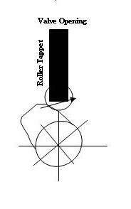
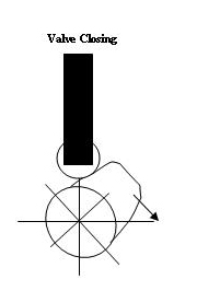
A single goal for increasing horsepower,  is to get more fuel into the combustion chamber quicker and exhaust the burned fuel out quicker.  Original C1 designed V8 engine incorporated the illustrated “flat-tappet” lifter which rode on the camshaft lobe as the camshaft rotated. It is apparent from the illustrations that a flat-tappet will open slowly (depending on the cam lobe slope) and close at an equal rate on the lobe downside.  IF, the valve could open quicker and close quickly the result would be more fuel being introduced and producing more horsepower when ignited during the power stroke.  This has always been the striving purpose in the hot rod world.

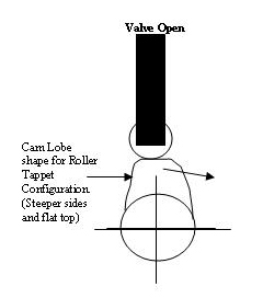
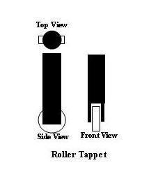
Friction is another factor in the original design that is obvious do to all rubbing/sliding mechanical parts.  The component rubbing generates internal friction in these engines resulting in higher heat and robbing horsepower.  An obvious improvement would be to incorporate a less friction medium.  The conclusion is a wheel/roller to ride on the cam lobe thereby reducing friction.  This is the thought process leading to the RTC, the technology incorporated in all current era engines.  A further improvement is also using rollers at the Rocker Arm resulting in further reducing friction.

Roller Cam 5Roller Cam 2Roller Cam 3

This RTC design also allows the design of a steeper slope on the cam lobes allowing a quicker opening valve and a flatter top cam lobe to maintain the valve open longer allowing more fuel to enter.  It is the best of all worlds.

Roller 1
RTC design operates similarly as the flat tappet configuration.  Significant changes where required in metal hardness and spring configurations due to the steeper cam lobe slopes.  The metal technology also is changed in the camshaft materials due to these higher tensioned valve train components.  The RTC components are available for converting the C1 engines and still have a stock-appearing exterior.  Review the following supplement handed out by speaker Doug Prince.  A complete conversion to RTC is recommended to be done by a professional engine shop as there is machining required on the cylinder heads, engine block, etc.

The following is a write-up provided by Doug Prince listing the parts needed to build your stock-appearing C1 Corvette RTC engine.
1957 283 C.I.-to-1967 327 C.I. Roller Cam Engines

Competition Cams Extreme Solid Lifter Roller Camshafts

1. MECHANICAL ROLLER – Good for weekend cruiser with 9:1 compression, has noticeable idle in smaller engines.  Camshaft part number 12-769-8, Camshaft grind number XR68R.  Duration at .050, intake 230, exhaust 236, valve lift: intake, .552 and exhaust .564.

2. MECHANICAL ROLLER – Great for power and overall engine torque, very easy on parts.  Rough idle in smaller engines, noticeable idle in larger engines.  Camshaft part number 12-770-8, Camshaft grind number XR274R.  Duration at .050, intake 236, exhaust 242.  Valve lift: intake, .564 and exhaust .570.

Required Parts for Proper Engine Assembly Using Stock Valve Covers

1. Crane Cams Gold Race Roller Rocker Arms, 3/8 Rocker Studs, part number 10750-16.

2. Crane Cams Gold Race Roller Rocker Arms, 7/16 Rocker Studs, part number 11752-16.

3. ARP 3/8 Rocker studs, 1.750 tall, part number 134.7101.

4. ARP 7/16 Rocker studs, 1.750 tall, part number 135.7101.  Same as Big Block Chevy.

5. Crane Cams Rocker Adjusting Nuts, short style, 3/8, part number 99788-16.

6. Crane Cams Rocker Adjusting Nuts, short style, 7/16, part number 99790-16.

7. Valve Springs, Competition Cams “beehive style”, part number 26120-16.

8. Valve Spring Seats, Competition Cams, part number 46797-16.

9. Valve Spring Retainers, Competition Cams, titanium, part number 794-16.

10. Solid Lifter roller Tappets, Crower Cams, severe duty, part number 66290-H16.

11. Chrome Molly push rods and guide plates are also required.

Recommended Cylinder Heads

1. All stock cylinder heads should be “pocket ported” with subsequent mild porting of the intake and exhaust ports.  Heads will require machining for enlarged valve springs screw in rocker arm studs, push rod guide plates and enlarged push rod holes.  Recommended valve sizes are 2.02 intake and 1.60 exhaust.

Recommended Exhaust Manifolds

1. Exhaust manifolds should be “port matched” to the cylinder head exhaust ports.  The 2 1/2 inch exhaust manifolds that first appeared on 1962, 327 cubic inch engines should be used when and where applicable.

Stroking of 283 and 327 Cubic Inch Engines for Increased Cubic Inches

1. Stroking of 283 and 327 cubic engines is highly recommended for greatly improved horsepower and engine torque.  Increasing the stroke of 283 and 327 cubic inch engines is relatively easily done today with readily available aftermarket parts.  Aftermarket parts are available from Scat Enterprises, Inc., 1400 Kingsdale Av., Redondo Beach, Ca. 90278.  Scat can provide brand new cast or forged crankshafts and forged connecting rods for your particular engine size.  Forged or cast aluminum pistons are available from many after market manufacturers.

Comparative Engines Built

1. 283 C.I. engine with 10.00:1 compression in a 1959 C1, close ratio four speed and 4.11 gears and stock Rochester FI.  Tremendous increase in power and could run with any 327 C1 or C2 Corvette.  This engine was built using camshaft number 1.

2. 283 C.I. engine with 12.00:1 compression in a 1960 C1 vintage race car, very, very expensive engine that produced 441 horsepower on the dyno with a ported and modified Rochester FI Unit.  This engine was built using a custom roller camshaft. Refer to Tech Session labeled War Paint in this Web Site for more information on this car.

3. 283 C.I. engine that was stroked to 327 C.I. with 10.00:1 compression in a 1961 C1.  This engine produced 347 horsepower on the dyno with a stock Rochester FI Unit.  This engine was built using camshaft number 1.

4. 327 C.I. engine that was stroked to 350 C.I., 10.00:1 compression in a 1956 C1.  This engine also had ported 2:02 heads and ported 2 1/2 inch exhaust manifolds with a stock Rochester FI Unit.  This car had a wide ratio T-10 four speed with 3.55 gears and would go sideways at half throttle in 1st, 2nd and 3rd gear!  This engine was built using camshaft number 1.

5. 327 C.I. engine that was factory rated at 365 horsepower.  This engine was stroked to 350 C.I. and made an astonishing 456 horsepower with ported cylinder heads and exhaust manifolds using camshaft number 2.

6. 327 C.I. engine that was factory rated at 360 horsepower.  This engine is currently in SACC member Vic Preisler’s 1962 Gulf Oil Race Car.  The cylinder heads were ported as well as the exhaust manifolds, 11.00:1 compression, stock Rochester FI Unit.  This car has a very noticeable idle at 1000 rpm and was built using camshaft number 2.

7. 350 C.I. engine that was stroked to 383 C.I., 10.00:1 compression, stock Rochester FI Unit, AFR aluminum cylinder heads and four tube exhaust headers.  This engine produced 453 horsepower at 6200 rpm using camshaft number 2.

Engine Builder

Quarter Mile Performance, aka, QMP Racing Engines

Brad Lagman, Owner

9530 Owensmouth Av.

Chatsworth, Ca. 91311

(818) 576-0816

Southern California Solid Axle Corvette Club

[/av_textblock] [av_button label=’Tech Topics Home’ link=’page,125′ link_target=” size=’small’ position=’center’ icon_select=’no’ icon=’ue800′ font=’entypo-fontello’ color=’theme-color’ custom_bg=’#444444′ custom_font=’#ffffff’]