|
Jeff Reade operates his own Corvette repair shop at 11375 Playa St. in Culver City, Calif., just east of the San Diego Fwy. Jeff brought all the props for explaining the rebuild process on the C1 Steering Gearbox. The Servicing Guide ST-12, mentioned above, contains all this information. Corvette Central sells a Steering Column Overhaul Kit (CC #561026 ’53-’57, or 561031, ’58-’62) for this task. Another kit was available in the past from Corvette Steering (which Jeff prefers) but it is no longer available. Some members may have this kit and you may be lucky and locate one. You cannot purchase some of the parts solely but only as a kit, however, always replace the steering Worm & Sector gear as a pair.
Why The Steering Gearbox?
Generally if operating correctly, the steering system on our C1’s is a very comfortable steering system and will provide a comfortable driving vehicle. The process for rebuilding the Steering Gearbox is to most owners, not a task to take on quickly and might not want to be approached unless necessary. However after Jeff’s discussion and how much impact this gearbox has on the whole steering system, the job might be reconsidered.
The Steering Gearbox is the first item in the C1 Steering System chain of components. When the steering wheel is rotated the gearbox controls the remaining items in the system. Steering System components are: Tires, Shock Absorbers, Kingpins, Tie Rods, 3rd Arm Member, Drag Link and finally the Gearbox. Each system component can contribute to a bad steering car and each component can be assessed individually. Several steering components will be discussed in future Tech Sessions and were only mentioned during this session.
The Steering Gearbox was presented because it really is the “heart” of the system and much time and money can be wasted on other components when the gearbox may be the primary problem. Most C1 owners are aware of items like tires, shocks, tie rods, alignments, etc. and shops and mechanics can address these issues but having problems in the steering gearbox will still not provide a comfortable steering car.
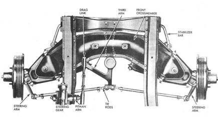
Many of our C1’s ,after being driven for many years (used and abused), have minimal attention paid to the Steering Gearbox. The usual C1 complaints are steering looseness, uneven (jerky) force while turning the steering wheel and the majority complaint “leaking lubricant”. These annoying items will motivate many to perform this task. No special tools appear to be required (unless a bearing seat must be removed) and can be done on the workbench.
Pre-ordering of parts, and seals is recommended to further speed this task along. The CC kit contains the parts required for the rebuild and as indicated earlier, some parts you cannot purchase separately. The CC rebuild kit cost is $430 but contains a new steering shaft/worm gear and sector gear. These items should be changed as a pair when doing the rebuild.
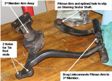
The steering gearbox, along with the steering shaft and mast jacket can be removed from a ’58 – ’62 C1 without major problems. Removing the hood, steering wheel, lower dash mast jacket cover support, left exhaust manifold and the front spark plug will allow the removal. Prior to the gearbox removal you disconnect the Pitman Arm (see pictures) from the drag link. The steering assembly can be tilted and lifted out the upper part of the engine compartment. Removing the hood makes the job easier but Jeff indicates the job can still be performed but the clearances for removal are tight.
Below Jeff Reade addresses the audience on rebuilding a C1 steering gearbox.
|
|
|
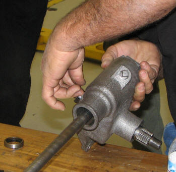
| The gearbox is shown below along with additional steering components to further understand what these steering items look like. |
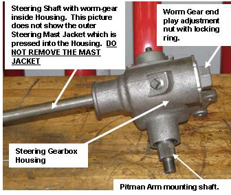  |
| The housing above shows the steering shaft but has the mast jacket removed. When the Steering Assembly is removed the mast jacket will be pressed into the Steering gear housing and should not be removed. The steering shaft and worm gear are removed when the Worm gear adjustment nut is removed on the end of the housing. Remove the Pitman Arm from the mounting shaft. This might require a puller which can be rented. |
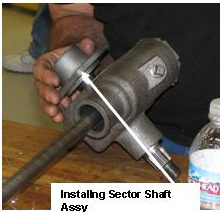 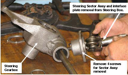 |
| Above indicates the removal of the Sector Shaft Assembly. 4 bolts retain the Assembly to the housing. The Sector Shaft is then removed from the interface plate. |
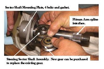 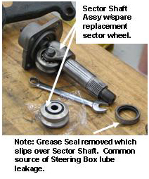 |
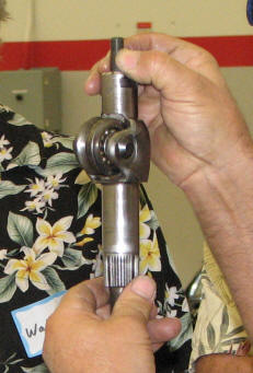
| The CC kit comes with a new Worm Gear and Sector wheel. The new wheel can be changed by removing the bolt and replacing the gear. Above is shown a new grease seal which will be reinstalled upon assembly. |
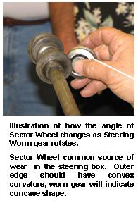 picture to the left illustrates the motion that the Sector gear moves inside the Steering Housing when the Worm Gear Rotates. This motion causes a common wear pattern over the years in the gearbox. You can inspect for wear on this gear by observing the outer surface of the gear should be a convex curvature. As wear occurs, this surface become concave and the steering becomes loose. This is the most important reason for replacing the worm with the sector as a pair. picture to the left illustrates the motion that the Sector gear moves inside the Steering Housing when the Worm Gear Rotates. This motion causes a common wear pattern over the years in the gearbox. You can inspect for wear on this gear by observing the outer surface of the gear should be a convex curvature. As wear occurs, this surface become concave and the steering becomes loose. This is the most important reason for replacing the worm with the sector as a pair.
Illustrated in the picture below. At the end of the Sector Shaft is a bolt which retains the shaft to the Plate assembly fastening it to the steering housing. The CC kit come with a new bolt which the head slips into a slot at the shaft end. Shims are also provided which can be slipped in and provide a snug fit for this bolt.
|
|
| Illustrated above right is the installation of the new worm gear assembly, and the Sector Assembly being fastened with the 4 bolts removed earlier. The new grease seal is installed and it is important to also use a thread sealant on the 4 bolts as leakage can occur at this interface. Install a new gasket and lube the internal gears and install new tapered bearings during assembly.The lubrication Jeff recommends is a high temperature grease, not 90 wt. transmission oil. A disc brake grease works. Prior to assembly it is also important to inspect the bearing surfaces inside the steering housing. Change out as needed. |
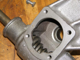 Illustrated to the left is the internal cavity of the steering housing with the new worm gear installed. The interface surface is the attachment surface for the Sector Assembly. Illustrated to the left is the internal cavity of the steering housing with the new worm gear installed. The interface surface is the attachment surface for the Sector Assembly.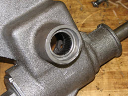
The surface to the left is the installation of a bearing and the new grease seal. |
| Adjustments during assembly: Review the adjustment in the ST-12 manual along with the following explanation.
Assembling the Worm gear into the steering box the primary adjustment is the end play nut on the end of the housing. Adjust the nut to remove any end play and turning the steering shaft aught to feel snug, not over tight. Install the Lock ring onto the adjustment nut and tighten.
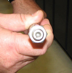
The Sector Assembly is installed with the gaskets and thread sealed bolts. The adjustment of the sector shaft end bolt is accomplished with the sector gear at the mid point of the worm gear. Orient the notch on the steering shaft end at the 12 o’ clock position and adjust the meshing of the two gears to be snug. Further adjustment can be done with the Steering Assembly installed in the car.
Reinstall the Steering Assembly into the car. Again orient the reference notch straight up and install the steering wheel on the shaft. Check for the force on the wheel while adjust the Sector Bolt. The force should be about 1lb. Refer to the ST-12 manual for a further discussion. |
  |
Post-Steering Alignment Check after installation of Rebuilt Steering Box.
1. Assuming the rebuilt steering box is properly rebuilt, and installed into
the car, connect the Pitman Arm to the Sector Shaft.
2. Point the Alignment mark, on the end of the worm gear shaft, straight up
(12 o’ clock position). This is the center travel position of the worm and Sector
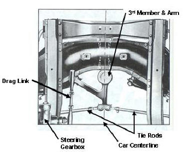
Shaft. Connect the Drag Link to the Pitman Arm and the 3rd Arm.
3. Establish a Centerline under the engine of the car. Two points of
reference are the center of the 3rd Arm mounting holes and the oil drain
4. Check the position of the 3rd Arm moving member which is attached to the Tie Rods. The centerline should go between the Tie Rod ends. If not, Adjust the Drag Link to establish this alignment.
5. Next verify the wheel alignment. If the alignment of Step 4 above is correct, the Tie Rods can be adjusted to establish the correct wheel alignment. An alignment shop can perform this, however make sure they begin the alignment with the correct steering wheel position.
|
|
|
|