Presenter: Chip Werstein
C1 Headlight Alignment
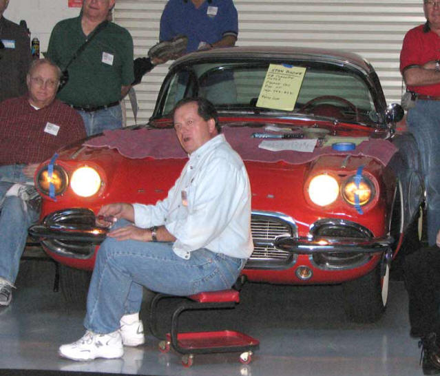
Chip Werstein is seen seated above lecturing about the first Tech Topic of the day, Headlight Alignment. Many of the So Cal SACC members may not travel out and drive their cars at night or some may do it often, but if you are out and turn your headlights ON and see that you are illuminating overhead cross street signs, while the LOW beam appears searching for crawling insects 3 feet in front of your car, you might want to read further and do this exercise.
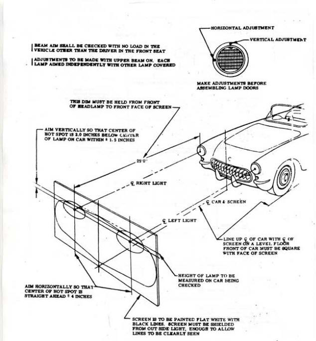
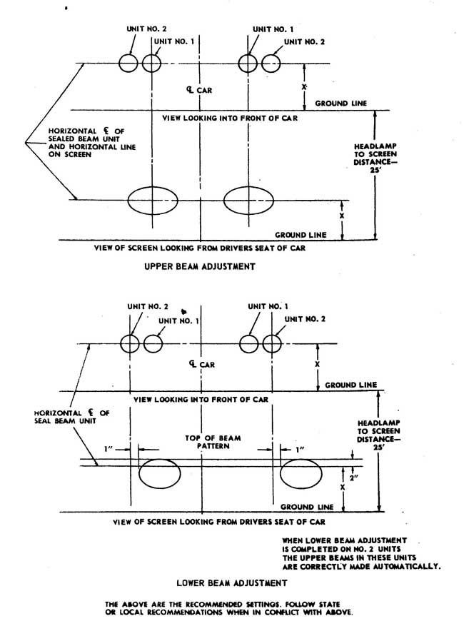
Chip selected Dwight McDonald’s ’62 for this alignment exercise. Chip’s initial handout for the factory Headlight alignment sheet is seen below. Other illustrations were originated by the Webmaster and entered for (hopefully) more clarification. Begin by removing both Headlight Bezel’s. This discussion is centered around the C1 Quad headlight design. A discussion on the C1 single headlight design follows at the end.
The drawing/layout above was a handout from Chip. Chip admits that it does require some understanding before performing the technique, since there is no step by step procedure provided. Below is the procedure followed by Chip during the session.
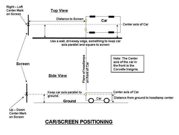
SQUARING THE CAR AND SCREEN POSITIONING: The placement of the car and the screen used for shining the headlights on is IMPORTANT! Begin in a location that is approximately 10 to 20 feet in length. The surface should also be level. “Square” the car to the Screen/Surface where the headlights will shine. The importance of this set-up places the surface to be illuminated parallel to the headlamps on the car. If this is not checked, the car could be pointed at an angle to the screen and the entire alignment is shifted off. A garage door can be used or the inside back wall of the garage, but the car alignment to whatever surface needs to be done correctly. Below is an illustration indicating the important measurements for positioning the car in front of a screen.
DISTANCE OF SCREEN: The screen distance from the car-front can vary. The diagram presented by Chip calls for 25 feet. The (you can check it out) headlight “lighted/illuminated” area/size gets larger as the screen distance increases. The closer the screen, the smaller the illuminated area. Also, it can be seen, the illuminated area is not a circle but is bigger in the left-right dimension. Sometimes a good compromise distance is 10 to 15 feet making the beam size smaller, and brighter.
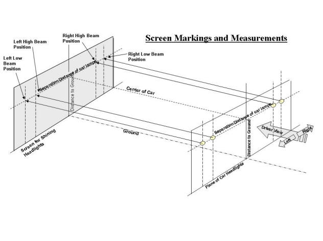
1. CAR POSITION AND SCREEN MARKS: Position the car on the level surface and “square” the car front to a surface/screen located over 10 in front of the headlights. Squaring the car front surface (imaginary plane containing the headlights) is important because the center of the car (Corvette insignia location) needs to be marked on the screen/surface (left-right and up-down measurement). Measure the distance from the ground to the center of your headlamps, locate this distance on the screen and adjust the left-right center location to be the up-down distance measured. Your final mark locations of the headlamps on the screen is found by measuring the location on the car. Remember, the up-down is the same as the center location. Your screen surface should now have marks identifying the center and all 4 of your headlamps (corresponding to the car lamp locations.
2. The diagram seen above indicates the Screen located in front of the car, and a “plane/surface” indicating the headlamps. The large arrows indicate the driver viewing direction in relationship to both screens.
3. HIGH BEAM ALIGNMENT: The first alignment will be the HIGH beam headlamp adjustment. These are the inner lamps on the car. Turn the HIGH beam ON in the car (all 4 lamps should be lit). Block off the outside lamps with some type of paper. This is indicated in the picture of Chip with Dwight’s car above. Using the two screws in the picture below (one for horizontal adjustment and one of vertical adjustment), turn the screws to locate the beam center (brightest hot spot) to be centered on the HIGH BEAM MARK position marked on the screen.
Vertical Adjust Adjust Screws
Horizontal Adjust Adjust Screws Inner (High Beam) Lamp Screw
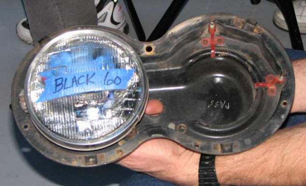
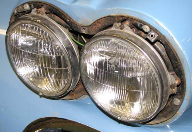
The pictures above are examples of C1 headlamp “bucket assembly’s”. Each lamp is secured into a framework of its own and secured in location with a stainless ring. The stainless ring/lamp/framework are secured into the double bucket assembly by springs and two adjustment screws. The double bucket is fastened to the car body. The 3 screws fastening the stainless lamp ring must be tight and are NOT adjusted. 2 additional screws per lamp, adjust the lamp angle and are indicated. One screw adjusts the vertical angle and the other screw adjusts the horizontal angle. They are indicated above.
4. HIGH BEAM ALIGNMENT (continued): Repeat step 3 on the remaining HIGH Beam Lamp. NOTE: When the car has the high beams operating (all 4 headlamps working), the outer lamps are not to be aligned when in the HIGH Beam operation. They are aligned in the following steps when in the LOW BEAM operation.
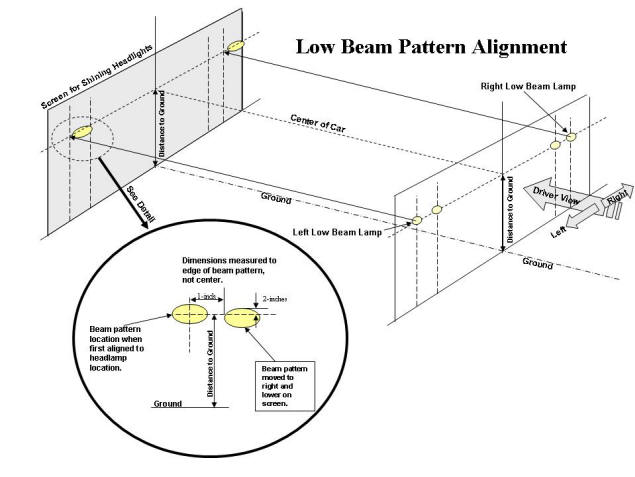
5. LOW BEAM ALIGNMENT: Switch the headlights to the LOW BEAM operation. Only the outer lamps should be working. As a first step, the pointing location of the Low lamps is straight ahead to the screen to the marks made when we started. Once the low beam lamps are aligned to the Low Beam marks, a further adjusted “desired” pointing will be done. See the chart below and adjust the Low beams slightly to the right (as viewed by the driver) on the screen, and slightly lower. A detail dimensioned sketch is indicated on the following illustration. BE AWARE when making the offset adjustment, the indicated offset is to the EDGE of the illuminated pattern, not the CENTER.
This “desired” last adjustment position provides more illumination on the highway/roadside for obstructions alongside the highway.
Align both LOW Beam lamps similarly.
Remember! You do not align the outer headlamps in the HIGH Beam operation as the change in any alignment when the outer lamps are switched occurs inside the lamp, so don’t mess with the outer lamp alignment.
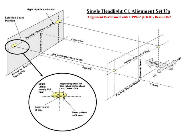
The following drawing was also supplied by Chip while at the Tech Session. This drawing contains alignment methodology for the single headlight systems incorporated on the 1953 to 1957 C1 Corvettes.
The adjustment procedure is very similar to the Quad headlight cars in car positioning, screen location, making the marks on the screen, etc. A significant difference is that this alignment is only performed with the Lamps in HIGH Beam operation. No alignment is done in the LOW Beam operation. A similar drawing below is another way of viewing the supplied alignment sheet.
Thank You to Chip Werstein for this presentation.
[/av_textblock]
[av_textblock size=” font_color=” color=”]
Click here to add your own text
[/av_textblock]
[av_button label=’Tech Topics Home’ link=’page,125′ link_target=” size=’small’ position=’center’ icon_select=’no’ icon=’ue800′ font=’entypo-fontello’ color=’theme-color’ custom_bg=’#444444′ custom_font=’#ffffff’]
