[av_textblock size=” font_color=” color=”]

4-spd. Shifter Refurbishment  IMG_6852

Presenter: Chip Werstein

Chip began this forum on the Shifter refurbishment with a short introduction about this mechanical, often over used and neglected, item which is the heart of our C1’s.  The impetus for this discussion was a malfunctioning shifter that  occurred while on a recent Chapter tour.  Some comments: 1) 1957 was the first 4-spd. shifter, 2) Road Tests usually were very positive as the unit was smooth, positive and well placed, 3) Comparisons of shifter assemblies are made to JAG, MG and Triumph shifters but the T10 gear box was fully synchro-meshed.

The Shifter Assy is rather simple having 50 to 60 moving parts but does have many moving parts with metal-on-metal contact which could introduce wear.  These units operate, and are often neglected without lubrication after initial installation.

Shifter Picture
4-spd-cmw a

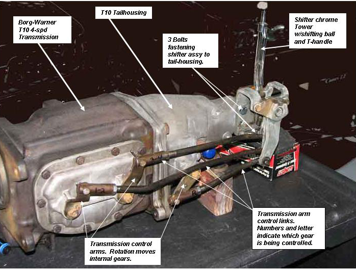
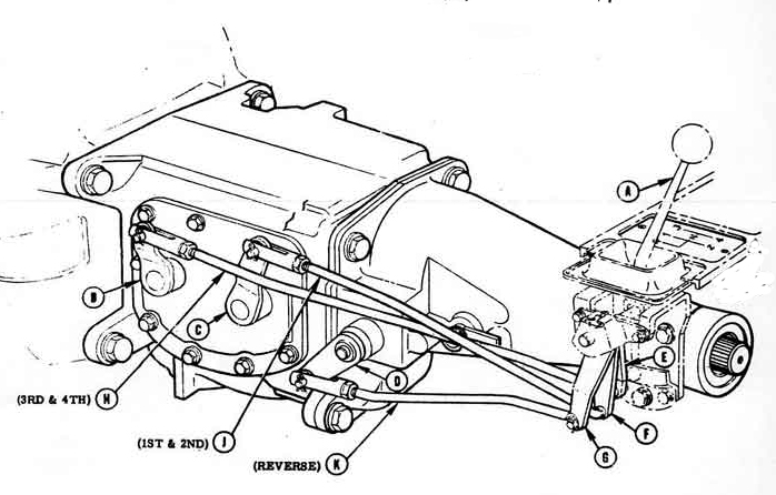
The above pictured item and illustration is a Borg-Warner T10 4-spd. transmission out of a C1 Corvette.  Mounted to the transmission tail-housing (using 3 bolts) is a 4-spd. shifting assembly which is used to control the gear selection while driving.  The chrome “tower” which extends straight up from the shifting assembly is the only component visible in the C1 passenger compartment.  The shifting assembly working components and transmission are located below the floor.

The shifting tower is capped off with a ivory colored ball and just below is the “T-handle” which when pulled up allows the shifter to select the reverse gear.  This T-handle is a reverse-lock-out to prevent accidentally shifting into reverse while using the 4 forward gears.

Most likely this shifter assembly refurbishment is performed on the work bench prior to transmission installation.  However, the shifter assembly can be removed from an operational car, leaving the transmission installed, and the unit refurbished on the bench.  The following technique is a process labeled as “Chip’s Way” which outlines a series of steps he has successfully used. 

Description:

In order to become more familiar with the transmission components, review the pictures and illustration above.  The labels on the picture indicate the shifter assembly, chrome tower w/T-handle, interconnecting rods/links between the transmission and shifter, and the bolts fastening the shifter to the tail-housing.  The shifter interconnect links are fastened to the transmission using clevis assemblies.  The links are then fastened to the shifter by a 90-degree bend in the link and spring clips.

3 bolts fasten the shifter assembly to the transmission tail-housing.   2 bolts are visible with the third obscured behind the shifter.  Accessing the shifter from below the car, with the transmission installed, is tight as the rear mount for the motor is just forward of the assembly.  The 3 bolts can be removed and one method suggested is to support the rear portion of the transmission and remove the motor mount.  Prior to removing the 3 shifter mounting bolts, disconnect the shifting links from either the transmission or from the shifter and the speedometer cable.  A 1/4 inch drive with extension and universal joint or swivel 9/16 socket will remove the bolts.

Notice that interconnecting rods extend from the shifter assy. to the arms on the transmission.  As the arms are rotated the gear selection is made inside the transmission.  Coincidentally, the links are marked, in the picture, with two numbers indicating which gears are being controlled by which link.  The furthest forward arm/link controls 1st & 2nd gear, the next rear arm is 3rd & 4th gears and finally the shortest link is Reverse.

The following procedure was supplied by Chip and it is “his way”.
Step 1: Remove the rubber shifting boot from the top, inside the car. Step 2: Crawl under car, or use a car lift, but disassemble the rods between the transmission and the control levers on the shifter assembly.  The Clevis end of the rods can be removed and/or the “Jesus” springs can be removed.  Keep the washers and any spacers that might be used.

Step 3: Remove the 3 bolts attaching the shifter housing from the transmission tail-housing.  This might require supporting and/or removing the transmission mount.  Remove the Shifter Assy.

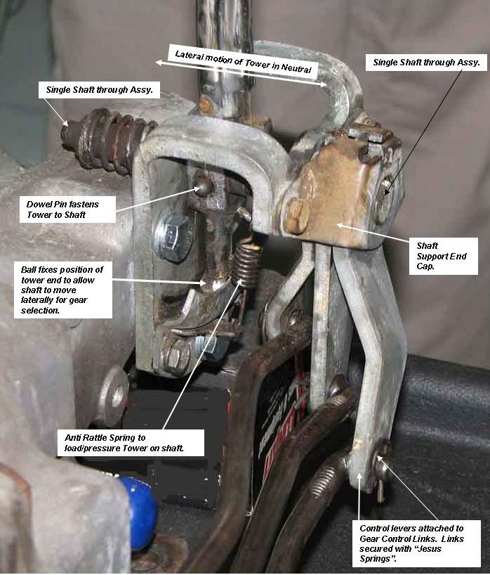
Below are close-up pictures of the shifter assembly.Note that all the shifting levers extend from a single shaft and the tower is also fastened to the same shaft using a dowel pin.  The lower end of the tower has a ball which fixes the side motion as the Tower is moved from side to side and will restrict the shaft motion to be side to side.  This side to side motion allows selection of one of the 3 shifter levers during gear selection.  A anti-rattle spring removes some looseness of the Tower by preloading the assembly.  The spring sometimes does fall off and the dowel pinning the Tower to the shaft sometimes must be replaced.  Two tower repairs are roll pins or in some cases a bolt/nut combination to replace the dowel.

Attaching the Shifting Links to the Shifter Levers is a slip fit with an item known as Jesus Springs.  Attaching, or removing, these springs originates the name when they go flying across the garage.  Leaving these Jesus Springs off is a source of rattle/vibration.

Shifter Picture 2
4-spd-bmw
Shifter Assembly, Disassembly (on bench).
During disassembly of the Shifter Assy: 1) The shifter links are disconnected from the Shifter Assy., 2) 3 bolts fasten the Shifter Assy. to the transmission tail-housing and the unit can be removed from below the car.  Previously, the shifter boot could be removed from the passenger compartment side.  Disconnecting the shifter links can be done at the clevis end or J spring end of the links.  Usually it is easier to remove the clevis end.

Step 1: Disassemble the Shifter Assy. on the bench.  Remove the anti rattle spring and the 2 bolts securing the lower tower ball guide plate. 

Step 2:  The shaft cross-shaft end cap (labeled in the picture) is removed with two bolts and the entire assembly can be disassembled.  Check the dowel pin looseness of Tower on shaft.

Step 3:  Clean all parts and inspect condition.  Inspect for wear.

Shifter Picture Parts
Prior to Reassembly:The items listed are small but are necessary to avoid vibration/rattling when installed in the car.

Clean the threads on the shifter link rods and clean threads inside of the clevis adjustments.  Also check threads on jam nuts which lock clevis adjustments.

Verify that you have the spring clips (Jesus springs) for the shifter links.  Order new clips if necessary.

Verify that there are spring washers which are installed on the shifter links at the clevis pin for later installation.

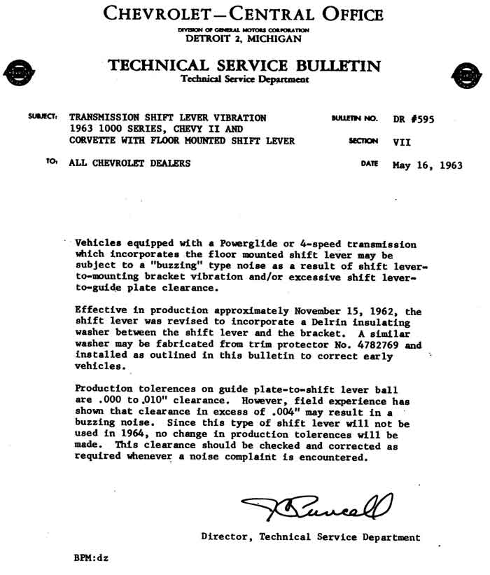
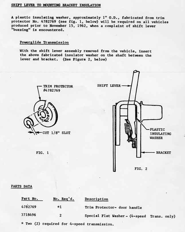
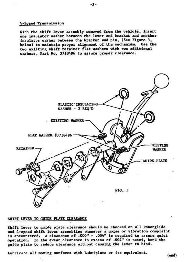
An additional item is indicated next which was a “fix” issued by Chevrolet on May 16, 1963.  The Technical bulletin is listed below for convenience.

Washer-aw
Washer-bw
Washer-cw
These slip-on insulators can be fabricated easily using the inside door handle (window or door) protectors. Lubricate all the shifter parts and the common shaft.  Chip’s recommendation is use an anti-seize compound.

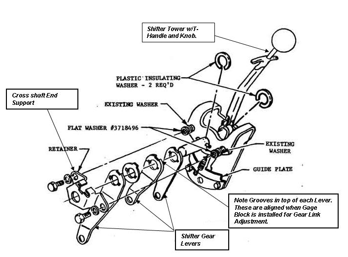
Reassemble the Shifter into frame and install nylon washers fabricated above.  Use the illustration layout to assist in the assembly of parts.  Install the tower lower guide and cross shaft end support.  Make sure the tower reverse lock-out is functional.

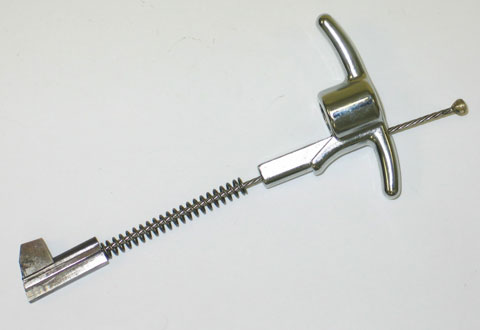
If the reverse tang is not functioning as the T-handle is squeezed, the tower must be disassembled and a rivet must be drilled out to accomplish this disassembly.  Internal to the tower is a part (available from Corvette parts suppliers) which most likely cannot be repaired.  This part is a cable spring assembly with the tang attached to one end.  Purchase a new part.  Install the new cable/tang spring assembly and a new rivet.

The Reverse Lock-out mechanism is internal to the Shifting Tower and is actuated by squeezing the T-handle on the tower.  When squeezing, the shifter is allowed to move over  to the left (drivers side) and engage the reverse gear.  Failure of the Lock-out requires removal of the tower and disassembly to replace the lock-out mechanism.  The picture below illustrates the Lock-out mechanism.


lockoutAs noted in the picture, a cable, T-handle, spring and lock-out lever are an assembly and the disassembly of the tower is required to replace this part.  The entire assembly is available from Corvette Central, part number 531111, and the cost is approximately $50.  Disassembly of the shifting tower is begun by removing the pin from the cross shaft and removing a dowel holding the tower together.  Once the new part is installed reassembly the tower, pin and a new pin fastening the tower to the cross shaft.
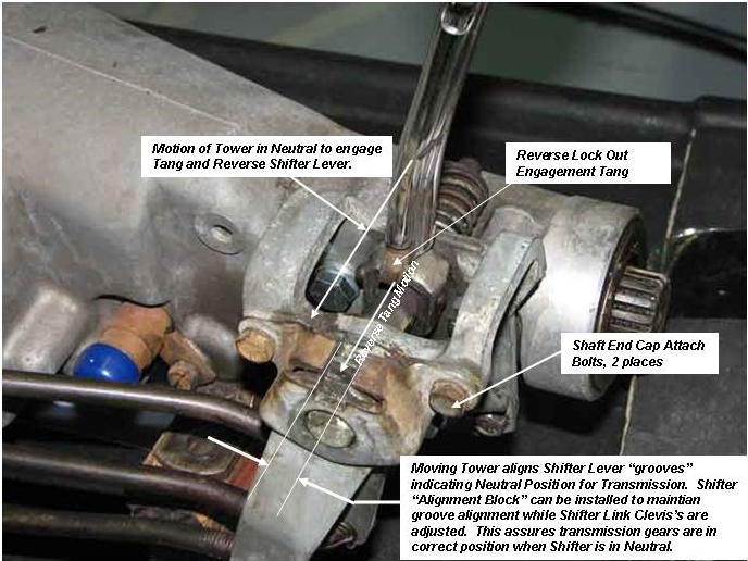
Understanding the shifter adjustment and the Reverse Lock-out.

The picture below shows the shifter in neutral position.  Another drawing below illustrates the concept also. 

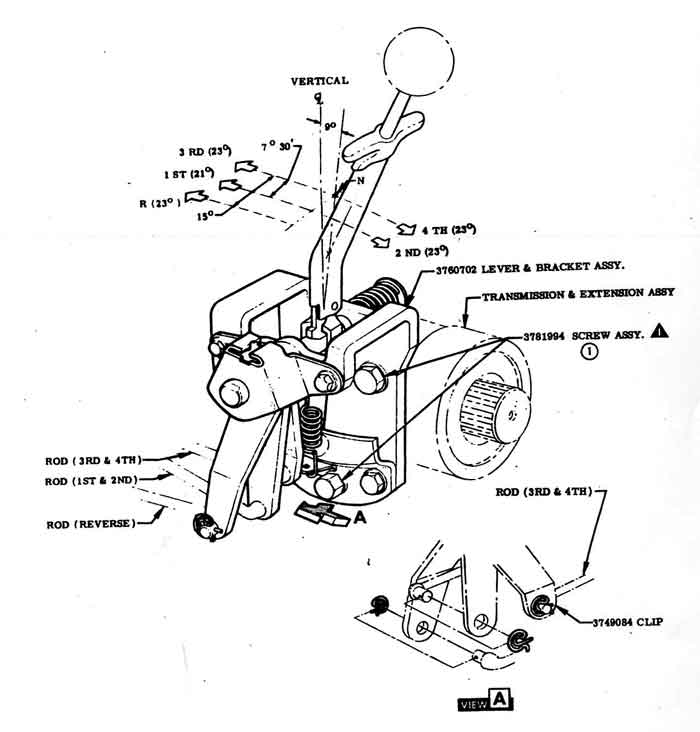
Notches are located in the upper part of each shifter lever arm that slips onto the shifter shaft.  When these notches are aligned (in the same position) the shifter assembly is in the neutral position, i.e. no gears are engaged.  As the picture below indicates, when the T-handle is squeezed the tang on the tower travels up and the tower motion can be moved away from the transmission and the tang will engage the outer shift lever resulting in the ability to move the tower forward and engage reverse.

The remaining adjustment is performed when the shifter is assembled to a transmission.  This adjustment will be the link/rod length adjustment.

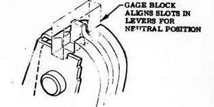
Place the shifting tower in the neutral position by noting that all the notches are aligned.  Insert theshifting adjustment block indicated in the drawing below.  This item is obtainable from Corvette parts suppliers.  The block is a very simple part and Chip provided these blocks at the meeting.

Once the block fixes the neutral position, the shifter levers and the rotating arms on the transmission are positioned in neutral.  The neutral position of the arms on the transmission are: forward gears rods are in a 12 o’ clock position (straight up) and reverse is rotated forward. Adjust the rod length by screwing the clevis’s to lengthen or shorten the link length.  A final check is to remove the adjusting block and shift through the gears. 

It is possible to perform the above adjustment with the transmission in the car but it is easier to perform the adjustment on the bench with the shifter attached to the transmission.  The final attachment of the clevis’s to the transmission should have the correct hardware: a pin, spring washer and cotter keys.  Lube the pins prior to inserting into the clevis.

Shifter Picture 3

Gage BlockThe above picture indicates a process to perform the Shifter Link length adjustment after refurbishment of the Shifter.  The drawing to the left will assist to indicate the correct installation of the gage block.  Each shifter lever arm contains a groove which is aligned with forward and rear motions of the tower.  When the groves are aligned, the gage block is installed and after setting the transmission gear levers to a neutral position (lever points straight up and down) the clevis ends of the links can be screwed CW or CCW to lengthen of shorten each link until the clevis fits.  The gage blocks were handed out for Free as Chip Werstein had them fabricated in quantity.  They are also available at a cost from most Corvette parts suppliers.
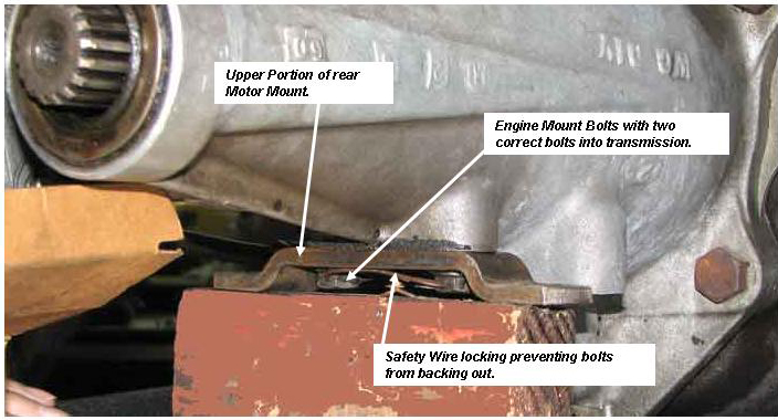
During the Q & A after Chip’s talk.  The two bolts fastening the transmission to the motor mount at the rear of the car are special bolts.  After installation, and you have the correct bolts with holes through the hex head, a safety wire should be added which is correct on original cars.  A picture below indicates this condition.Shifter Picture d
Thank You to Chip Werstein for this presentation.

Southern California Solid Axle Corvette Club

[/av_textblock] [av_button label=’Tech Topics Home’ link=’page,125′ link_target=” size=’small’ position=’center’ icon_select=’no’ icon=’ue800′ font=’entypo-fontello’ color=’theme-color’ custom_bg=’#444444′ custom_font=’#ffffff’]